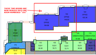
Non-CAD users can add redlines to drawings to indicate location areas directly on a floor plan drawing. Once you add redlines, the system saves them as a document. Other users can access the redlines using the system's document management features. For example, a user might access a document to review an image of the floor plan with redlines such as the following:

You cam add redlines to drawings in order to:
Many types of users benefit from adding redlines to drawings. For example:
When working in applications such as EH&S, Service Desk, or On Demand Work, you can add redlines to the floor plan drawing to indicate the location of an item. For example, if you have done a complete survey of the floor, you might find that the as-built drawing is no longer correct, you can create a service request and make redlines on the floor plan drawing to indicate the changes that need to be made.
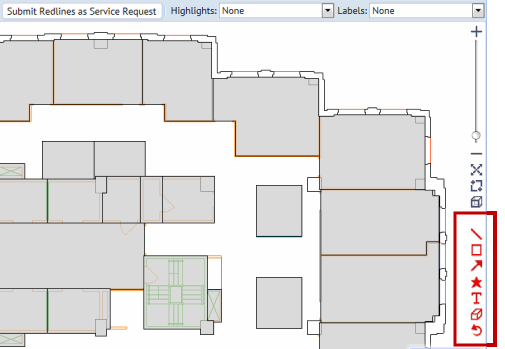
Tasks for which you may want to add drawing redlines launch drawing frames that include the redline tools on the right edge of the drawing frame.

Note the following:
Before adding the redlines, you may wish to focus on an area by zooming and panning. Or, you may wish to display room numbers or other highlights. For information, see Working with Drawings.
When you save redlines, the program saves the view of the drawing currently on the screen - including highlights, labels, and redlines - as a .png image file. If you select Save when you have zoomed in, and not all redlines are visible, a pop-up window appears asking if you want to keep the current view or zoom out until all redlines are visible, and then save the image file.
The image file containing the redlines is uploaded to the appropriate document field of the parent item (such as a service request or incident report) as a file attachment. Users can view the redlines by choosing it from a task that presents the document field.
The system saves the redlines as vectors in the in the ARCHIBUS Redlines table along with all data needed to regenerate the redlined floor plan.